(C) 2009 Hank Wallace
If you troll amp makers’ web sites, you will find some comments about the construction of their amplifiers. Some proudly use only point-to-point, hand-wired techniques, and some use printed circuit boards.
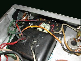
The hand-wiring proponents aim to build amps like they were built in the old days, by soldering components to terminal strips or wiring boards, using discrete lengths of insulated or bare wire when needed to make connections. The intent, of course, is to reproduce the sound of yesteryear by reproducing the construction techniques of yesteryear.
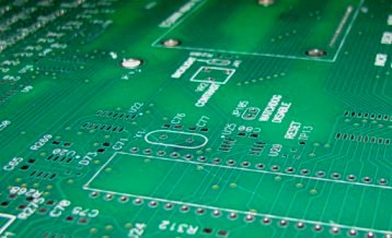
The printed circuit board (PCB) proponents aim to create a good sounding amplifier less expensively. There are actually machines that can bend the leads on components and insert them into PCBs, drastically reducing labor costs and increasing repeatability in manufacture. Components these days are shipped in reels of thousands of parts. The automatic insertion machines pluck parts off these reels and stuff them into each PCB, and there is very little chance of putting the wrong part in the wrong holes on just one or two out of a lot of 1000 PCBs, as there would be with hand construction.
Some such errors would be impossible to find, say, if you swapped a 10K and a 47K resistor in a hand-wired tube amp. The amplifier would work, but it would sound somewhat different from it’s sister. You might or might not notice, but there would be a difference depending on the values of the components involved. The difference might even reduce the reliability of the amplifier. This makes detailed visual and electronic inspection of hand-wired amplifiers very important. (And many manufacturers do tedious visual inspections to guard against such mistakes.)
So aside from the cost difference, what distinguishes PCB and hand-wired designs? The hand-wired crowd would say that there is less capacitance between conductors in a hand-wired amp, since most of the connections are separated by air instead of the fiberglass of the PCB. This is true, but it really only matters for a few signals on an amplifier schematic. For example, the grid circuits in a tube amp should be wired for minimal capacitance (few surrounding conductors), as this capacitance can roll off the high end of each stage. The cathode, plate, suppressor, and screen grid circuits are not nearly so sensitive.
Also, the inter-circuit capacitances in hand-wired amplifiers will vary from unit to unit much more than in PCB based amplifiers, simply because the conductors on the PCB are rigidly fixed.
However, as with many things amp, these internal capacitance factors do not matter because each amplifier has a row of knobs on the front panel (TONE CONTROLS) that change the frequency response 15dB or more in two or more frequency ranges! Small variations in capacitance in the circuit do not prevent the player from dialing in his preferred tone.
The issue comes down to one of cost. PCB based circuits are cheaper to mass produce, and are easier even to build by hand. I have decades of experience with this, building everything from audio circuits, radios and high powered burn-in gear, to tiny microprocessor devices, and if it’s going to take me some hours to wire a circuit I’ll generally just lay out a PCB and be done with it. The computer routes the copper traces for me in a few minutes, and I only have to inspect the result for compliance with sound engineering practice.
If I need a certain capacitance on a certain point in the circuit, I can design the PCB to make it happen. Any point-to-point circuit can be rendered as a PCB design with exactly the same performance, if the designer is competent. If I can design a radio circuit with a bandwidth of GIGAHERTZ using a PCB, where an extra 5 picofarads of capacitance can render the entire thing useless, then I can successfully design an audio amplifier using a PCB.
A related matter is the type of solder used to make connections. Amps of old were typically constructed using tin/lead solder. However, lead has been banned in electronics manufacture over most of the planet, so manufacturers have been using tin based solder for some time now. If you want that old time sound, you have to use the old time parts and solder, right? Well, no, as long as the connections are low resistance, and they certainly can be as good using tin solder. But that’s a point where environmental regulations are working against the vintage amp builder, at least when he wants to sell his products into countries which have banned lead solder.
And it is of course silly to insist on a hand-wired amplifier, then drive it with a pedalboard loaded with ‘vintage’ pedals which are the very incarnation of sloppy circuit board workmanship. When I was a young whippersnapper, friends used to ask me to repair their stomp boxes. Almost always the problem was a cracked solder joint on an audio or power jack, where the pins entered the circuit board, though sometimes there was a cold solder joint on a connection from the factory. These products were all made in Japan in the 1970’s and the quality was very poor. The circuit boards were all single-sided (copper on one side only) which led to conductor routing contortions in the name of low cost. But these pedals today are the holy grail of tone! So a guitarist buys a hand-wired amp for $$$, then plugs a yesterday-cheap-but-today-expensive, poorly made pedal into the front end, touting the high class construction of the amp. Where has common sense gone?
If the guitarist likes the tone of that combination, no problem, but let’s not attribute it to the use or not of hand wiring techniques.
These days if you are constructing a killer amplifier, you can have high quality PCBs made for some $30 to $50 each in low volume (5-10 pieces, see Advanced Circuits or Sierra Proto Express), so it makes no sense to spend 10 hours hand-wiring each amplifier when you can buy a PCB, and stuff and solder the parts in just an hour or two per amp. No sense. If you purchase PCBs in larger lots, the price drops quickly.
I expect a lot of the hand-wiring techs simply do not know how to lay out PCBs, and this keeps them working in the 1950’s. But designing PCBs is not difficult, and there are so many educational resources online. There are books you can purchase on PCB design (search for “printed circuit design” at Amazon.com). Take a look at the IPC standards, which cover design and construction of PCB assemblies. You will have to be careful about spacing of copper traces due to the high voltages involved, but there are basic rules that govern those things. For example, Underwriter’s Laboratories publishes specifications that state what such spacings should be, as in UL 840, “Insulation Coordination Including Clearances and Creepage Distances for Electrical Equipment.” See the UL web site.
Some PCB design programs are free (see Eagle), and you can upload the design file to the fabricator easily to have some PCBs made. If you are PCB-phobic, don’t be — take the plunge and try your hand. You have the electronics background to do a good sounding circuit design; you can certainly learn this!